Setting Up the BeagleBone Black's GPIO Pins
This post will detail how to set up the BBB’s GPIO pins. General Purpose Input/Output (GPIO) pins are special in that they can be configured at runtime to perform in a variety of ways, ranging from simple i/o to serial interfaces to specialized encoder readings. While the BBB supports up the 69 gpio pins, in reality the majority of the pins are being used by onboard system processes such as the board’s HDMI and LCD abilities. This post will detail the steps necessary to take advantage of these otherwise inaccessible pins, as well as configure a gpio pin to suit the user’s needs.
Linux Kernel Version
This guide assumes the user’s BBB is running Linux Kernel 4.1.15. If an earlier version is used, such as 3.8.X, then abundant information on configuring the BBB can be found through google and the procedures listed in this guide will probably not work.
BBB Headers and Pinout
The BBB has two 23 pin columns on each side of the board, for
a total of 92 pins available to the user. The right header is
designated as P8 while the left is designated P9. Pay careful
attention to the orientation of the BBB in reference to the pinout
numbers, else you risk mis-wiring the board and potentially causing
irreversible damage. Physical pins are numbered in the following
manner, PX_Y, where X is the header where the pin is located (8 or
9) and Y is the location of the pin with that header. Pins P8_1
and P9_1 are located at the top right of each header. Notice that
the left column of each header are all the odd pins while the right
column of each header are all the even pins.
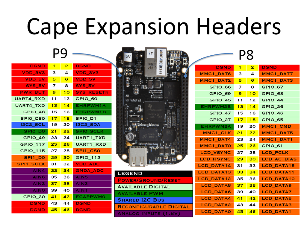
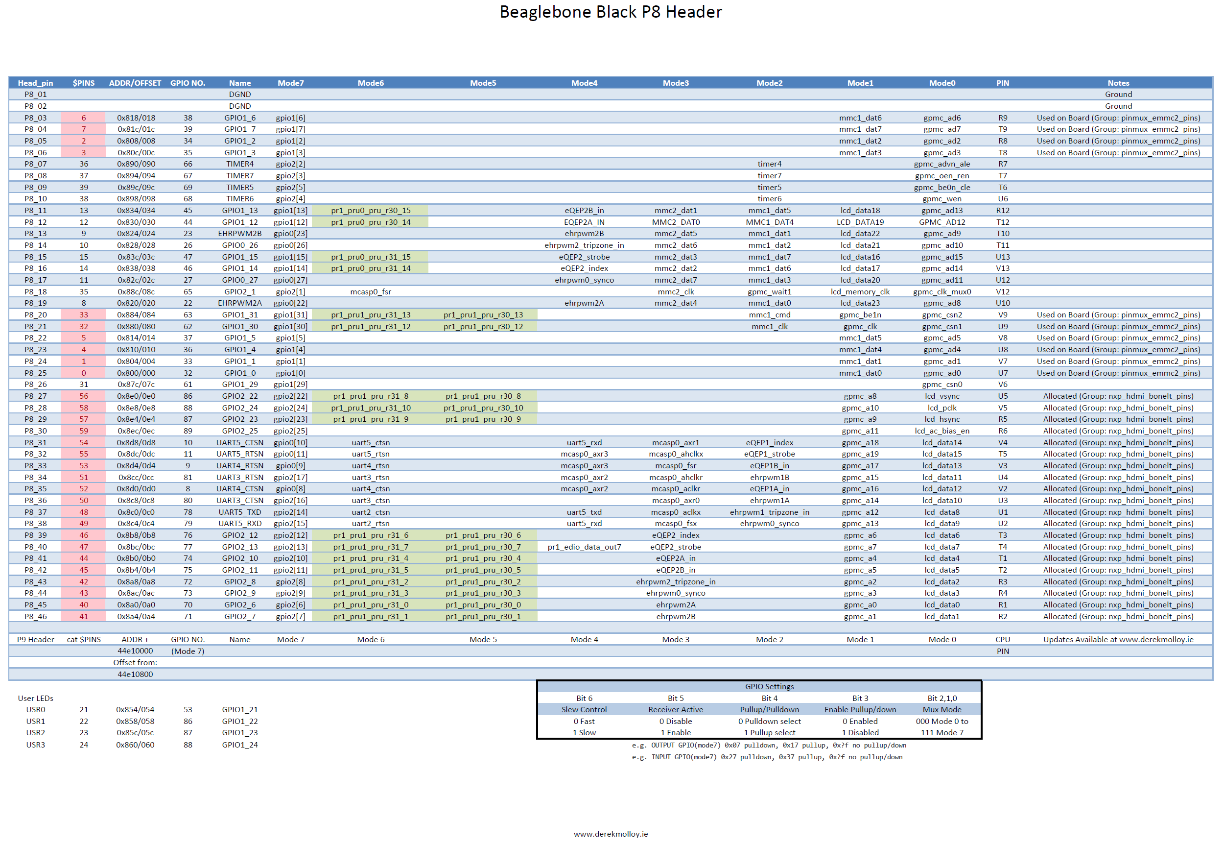
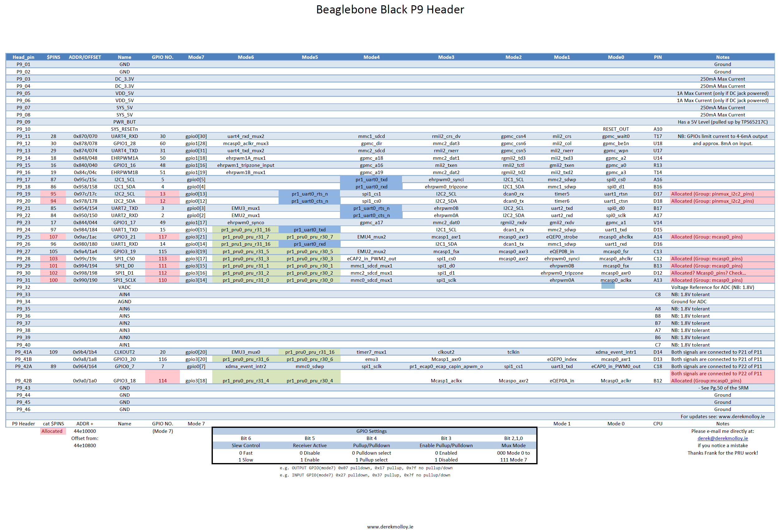
As seen in the graphic, the first and last rows of pins are dedicated to nets such as DGND, VDD_3V3 (3.3V Output), VDD_5v (5V Output), and system power/reset. The rest of the pins are configurable in software, as will be detailed later in this post. The labels on the graphic show the default mode of the pins. Not all pins are able to be used as GPIO’s immediately. Systems such as the LCD and HDMI drivers take priority to these pins. A more detailed view of the BBB’s header’s and pin usage can be seen in the graphics below
GPIO Numbering Scheme
The gpio pins of the bbb are grouped into 3 groups of 32: GPIO0,
GPIO1, and GPIO2. An individual pin can be refered to using the
convention GPIOX_Y where X is its gpio register and Y is its
number within that register. However, all references to a particular
pin made in software instead uses its absolute pin number! A gpio’s
absolute pin number is calculated in the following manner: Z =
32*X + Y where X is again the gpio register and Y is the position
within that register.
i.e. GPIO2_24 is 32*2+24, making it GPIO_88. If this pin were to be
referenced anywhere in software, the user would use the number 88, not
24!
Overloaded Pins
Additional scrutiny of the above header pin layouts shows all the
possible uses of each individual pin. Any pin highlighted in red is a
pin that is inaccessible for use as a gpio pin by default, see the
notes column for it’s initial allocation. As an example, P8_28, aka
GPIO2_24, aka GPIO_88, is by default allocated to the
nxp_hdmi_bonelt_pins group. While it is overloaded in this capacity,
no other use can be made of this pin. Multiple modes are available for
each pin, and setting these modes wil be discussed in a later section.
Recap of Numbering Schemes
As a recap, each gpio pin on the BBB has three different numbering schemes associated with it!
- The physical pin location, in the form of
PX_Y(P8_28) - The gpio name, in the form of
GPIOX_Y(GPIO2_24) - The gpio number, in the form of
32*X + Y(88)
Only the last scheme, the gpio number, is used in software!
Configuring Accessible GPIO Pins
Once a GPIO pin is accessible (either by default or by configuring a device tree overlay as detailed below), it is very easy to intereact with it directly from the terminal. First, simply for ease of life, enter the following command to temporarily switch to root for this example.
sudo su
We interact with BBB pins via a set of files that are read/written to. To reach the directory where these files are located, enter the following.
cd /sys/class/gpio
echo 27 > export
cd gpio27
echo out > direction
cat value
echo 1 > value
Access using C++ library
The C++ library can be found here.
#include "gpio.h"
~~~
~~~
unsigned int pin = 27;
gpio_export(pin);
gpio_set_dir(pin,OUT);
gpio_set_value(pin,1);
Accessing Inaccessible Pins
Before going into the details of configuring inaccessible pins, it is necessary to briefly go over the inner workings of the BBB and touch on concepts such as pin modes, the device tree and its overlays, and how to interact with it.
Pin Modes
As seen in the above graphics detailing the P8 and P9 headers, each pin can be configured to one out of 8 possible modes. For our purposes, it is important to note that mode7 is always the GPIO configuration for every pin.
The pin mode for any given pin is stored in 7 bits using the following convention.
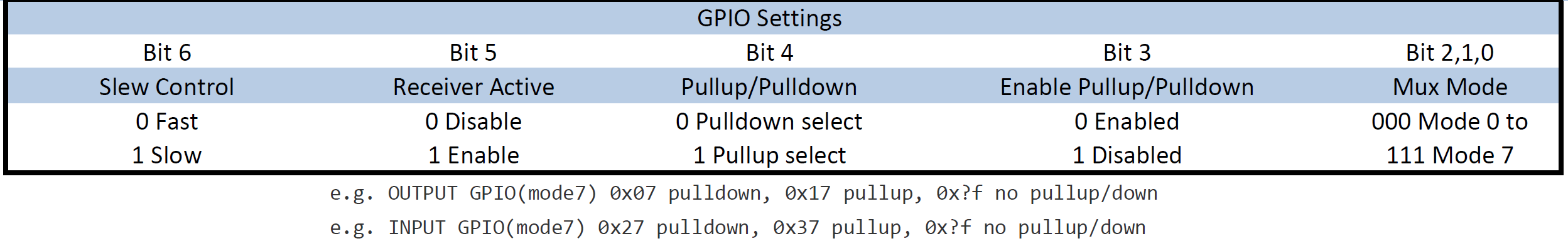
Notice the example configurations under the table. The bits values are listed in Hexadecimal form, so that the two digits following “0x” contain the values of all 7 bits. The last digit of the pair contains the values of bits 0,1,2, and 3. As such, in order to be in mode7 (GPIO) bits 0,1, and 2 are all 1, giving a possible value of either 7 or F for the last hex digit. (Binary of either 0111 or 1111). The first digit of the pair contains the values of bits 4,5, and 6 (with the most significant bit being a constant 0). If the pin is configured as an output, then the possible values of this bit are 0 and 1 (0000 and 0001) depending on if pull down or pull up is selected. If the pin is an input, the possible values are 2 and 3 (0010 and 0011), again depending on the pullup/down setting
The pin mode of each pin is configured in what is called a device tree overlay, which will be discussed in detail in a later section.
Device Tree
Here is a good overview of what exactly the device tree is. BEWARE, THIS LINK IS for the 3.8 KERNEL AND IS NO LONGER COMPLETELY ACCURATE!
The Linux Device tree controls the configuration of pins: mux mode, direction, pullup/pulldown, etc. It is a generic, standardized way of dealing with constantly updating hardware configurations. In short, it describes the hardware in a system. It is the linux version of ARM board files.
The device tree is compiled into a .dtb file that is then loaded
upon the kernel’s startup. All specified pins and peripherals are
loaded and configured for use in the system.
Cape Manager and Device Tree Overlays
As mentioned in the previous section, the device tree is loaded when the kernel starts. It would be a very long and tedious process if, in order to make any changes to the device tree, one were required to modify the device tree, recompile it, and restart the device. Luckily, the BBB’s cape manager comes to the rescue. The cape manager allows the modification of parts of the device tree at runtime by loading overlays that enable peripherals or mux pins to a specific function.
To see what device overlays are currently loaded on the device:
cat /sys/devices/platform/bone_capemgr/slots
As an example, one might see the following:
root@node31:~# cat /sys/devices/platform/bone_capemgr/slots
0: PF----  -1
1: PF----  -1
2: PF----  -1
3: PF----  -1
4: P-O-L-   0 Override Board Name,00A0,Override Manuf,BB-ADC
5: P-O-L-   1 Override Board Name,00A0,Override Manuf,gpio_88
This shows that two overlays, BB-ADC and gpio_88, have been loaded by the cape manager.
In order to check if an overlay has successfully changed the pins modes of the target pins, utilize the following commands:
cat /sys/kernel/debug/pinctrl/44e10800.pinmux/pins
/sys/kernel/debug/pinctrl/44e10800.pinmux/pins will provide the pin
number, the pin’s physical memory address, and the current mode to
which the pin has been muxed.
cat /sys/kernel/debug/pinctrl/44e10800.pinmux/pingroups | less
/sys/kernel/debug/pinctrl/44e10800.pinmux/pingroups provides a list of all “claimed” pins, such as pins that are configured and reserved via overlays.
DTC And Compiling Custom Overlays
In order to make custom overlays, it in necessary to install the device tree overlay compiler made and maintained by Robert Nelson. It can be found at https://github.com/beagleboard/bb.org-overlays. For ease of use, we have forked the current version at https://github.com/VADL/bb.org-overlays, so that as long as you are running the 4.1.15 kernel, compatibility is not an issue.
To install the compiler, perform the following steps.
- clone the dtc repo
git clone https://github.com/vadl/bb.org-overlays
cd ./bb.org-overlays
- Run the dtc-overlay script
./dtc-overlay.sh
After installation, the dtc compiler can be called on a .dts file to produce the corresponding .dtbo overlay file. For an example overlay called sample_overlay.dts:
dtc -O dtb -o /lib/firmware/sample_overlay-00A0.dtbo -b 0 -@ sample_overlay.dts
Be sure to put the new .dtbo file into /lib/firmware so that it is
visible to the BBB os. ALWAYS APPEND ‘-00A0’ TO THE END OF A DTBO
FILE. THIS IS NECESSARY FOR THE FILE TO BE LOADED PROPERLY BY THE CAPE
MANAGER!
One minor yet crucial tidbit of knowledge to remember is that the overlay name cannot exceed 14 characters. If this limit is exceeded then it will not be able to be enabled by the cape manager.
To enable the overlay, type the following
echo sample_overlay > /sys/devices/platform/bone_capemgr/slots
| Note that the name of the cape in this command is just sample_overlay, not sample | _overlay.dtbo |
To set the overlay to enable at boot, add the cape name in /etc/default/capemgr
cape=[comma delimited cape names]
Documentation on this can be found here
Disabling Default Overlays
Enabling and Disabling Custom Overlays
Related Concepts
PRU
Reading and writing the gpio pins through the file system as detailed above is a relatively slow process, capable of read/write frequencies in the low hundreds of Hz. An alternative is to utilize the BBB’s built in Programmable Realtime Units (PRU’s). PRU’s are independent units completely separate from the BBB OS, and can allow I/O at up to 20 MSPS. While this guide does not detail how to use a PRU, don’t forget it exists!
A GitHub repo supporting PRU use can be found here
Ken Shirrif has a blog post on the PRU here
Analog I/O
Serial and UART Communication
Links
A writeup about BBB Overlays and the cape manager can be found here
Ken Shirrif’s blog has a great post on the BBB GPIO
In addition to providing many of the graphics used in this document, Derek Molly has extensive documentation on all things BBB